Design and FEM Analysis of Navigation Grade Low Noise and High Sensitivity Capacitive MEMS Accelerometer based on SOIMUMPs Process Constraints
Description
the design of a single DoF capacitive MEMS accelerometer considering the commercially available microfabrication process constraints. The microfabrication process considered for the design optimization is SOIMUMPs process with silicon material and structural layer thickness of 25 μm. The performance of the MEMS accelerometer is analyzed using both analytical and finite element method (FEM) based simulations. The proposed design offers high sensitivity, low noise, and resolution of 2 mg for an input acceleration range of ±50 g. The high mechanical and capacitance sensitivity is achieved by designing the symmetric suspension beams, utilizing the maximum area on the periphery of the proof mass and gap-antigap based differential capacitance sensing. The proposed design is ready for fabrication, with performance parameters that meet the requirement of its use in navigation grade defense applications.
<-- A detailed analytical model,
considering the dynamics of both the electro-thermal actuator and multi-mass system, is developed.
A parametric optimization is carried out, considering the microfabrication process constraints of the
Metal Multi-User MEMS Processes (MetalMUMPs), to achieve high gain. The stiffness of suspension
beams is optimized such that the sense mode resonant frequency lies in the flat region between the
first two resonant peaks in the drive mode. The results acquired through the developed analytical
model are verified with the help of 3D finite element method (FEM)-based simulations. The first
three resonant frequencies in the drive mode are designed to be 2.51 kHz, 3.68 kHz, and 5.77 kHz,
respectively. The sense mode resonant frequency is designed to be 3.13 kHz. At an actuation voltage
of 0.2 V, the dynamically amplified drive mode gain in the sense mass is obtained to be 18.6 µm. With
this gain, a capacitive change of 28.11 f F and 862.13 f F is achieved corresponding to the sense mode
amplitude of 0.15 µm and 4.5 µm at atmospheric air pressure and in a vacuum, respectively.
Operating Principle
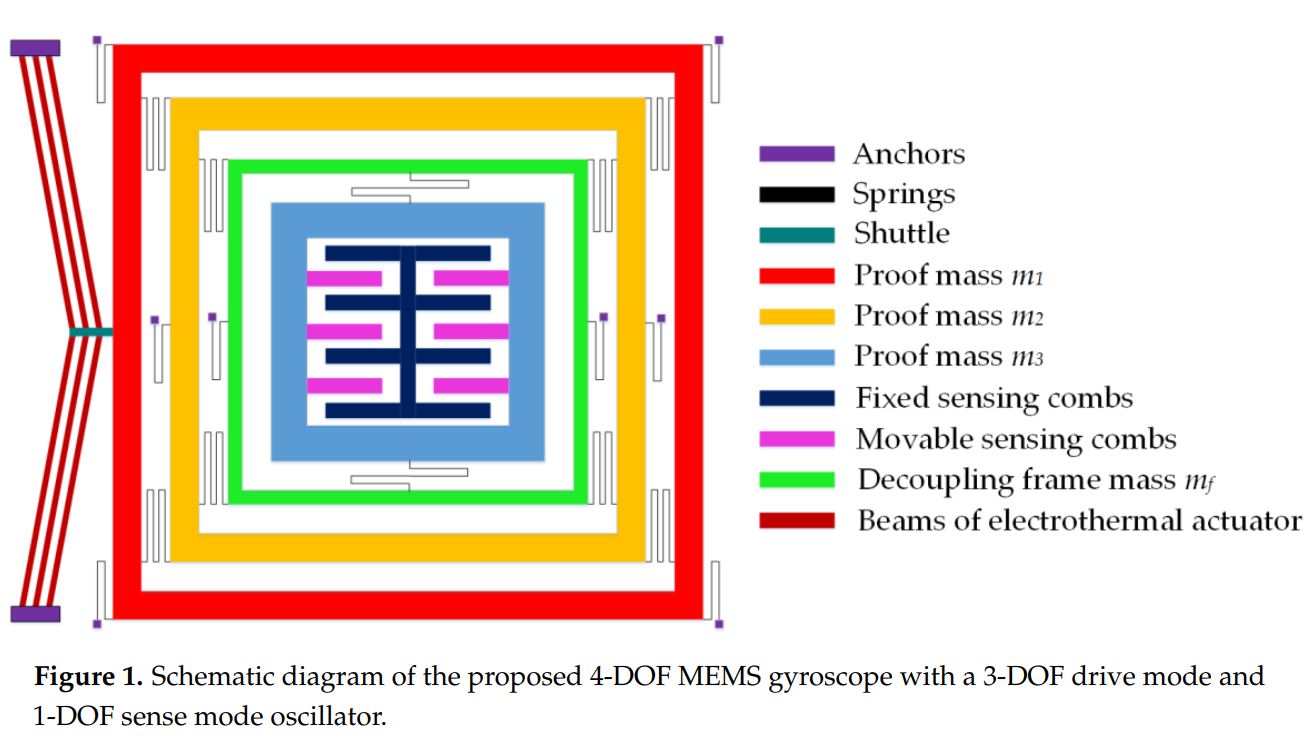
Fig. 1 shows the schematic of the proposed single-axis
MEMS accelerometer design. The material of the whole structure is Silicon with structural layer thickness of 25 μm.
The design consists of a rectangular proof mass which is suspended through serpentine shaped suspension beams,
acting as mechanical springs. Since the transduction mechanism is capacitive, rectangular combs are attached to
the top and bottom of proof mass which act as capacitors. Unlike the designs reported previously on single-axis
accelerometers, extra combs are also attached on the branch segments of the proof mass, to increase the capacitance
change. The other end of the mechanical spring is attached with the anchor, to which stator combs are also attached. The
stator and rotor combs are kept in gap-antigap configuration to obtain maximum capacitance change. To prevent the
damage of the design due to the collision of rotor combs with stator combs during input shock acceleration or pull-in effect,
circular shaped end stoppers are also designed and attached to the anchor. The combs on the top and left side of the proof
mass make one set of capacitor pairs and those present on the bottom and right side of the proof mass make second capacitor
pairs. These two sets of capacitor pairs will work in gapantigap configuration during the motion of the proof mass
corresponding to an input acceleration. For the working of accelerometer, a bias voltage is applied to these two sets of
capacitor pairs and the proof mass is grounded. For this purpose, the electrical isolation is included in the MEMS
accelerometer design.
The proposed accelerometer can be modelled using a conventional mass, spring and damper system as shown in
Fig. 2. Following Newton’s second law of motion, under an input acceleration, the proof mass of the accelerometer
undergoes a displacement from its rest position and magnitude of this displacement is proportional to the input acceleration.
Hence, the modelling can be done using a second order differential equation which is given as:
mxሷ+cxሶ+kex=ma cos ωt (1) where m is mass value of the proof mass, c is the damping
coefficient, ke is the stiffness of the suspension beams and a is the magnitude of input acceleration with frequency ω, which
results in displacement of proof mass with magnitude x. By solving (1) and considering x(t)=xcos (ωt െ α), the equation
for the displacement of proof mass can be written as:
FEM Simulation Results
a FEM-based natural frequency analysis is carried out. The boundary conditions and material
properties are input parameters while mode shapes and resonant frequencies are the output responses of the modal analysis. The structural parts are modeled using Solid 98 elements. The optimized mesh
size is selected based on patch conforming algorithm for tetrahedrons method control. The desired
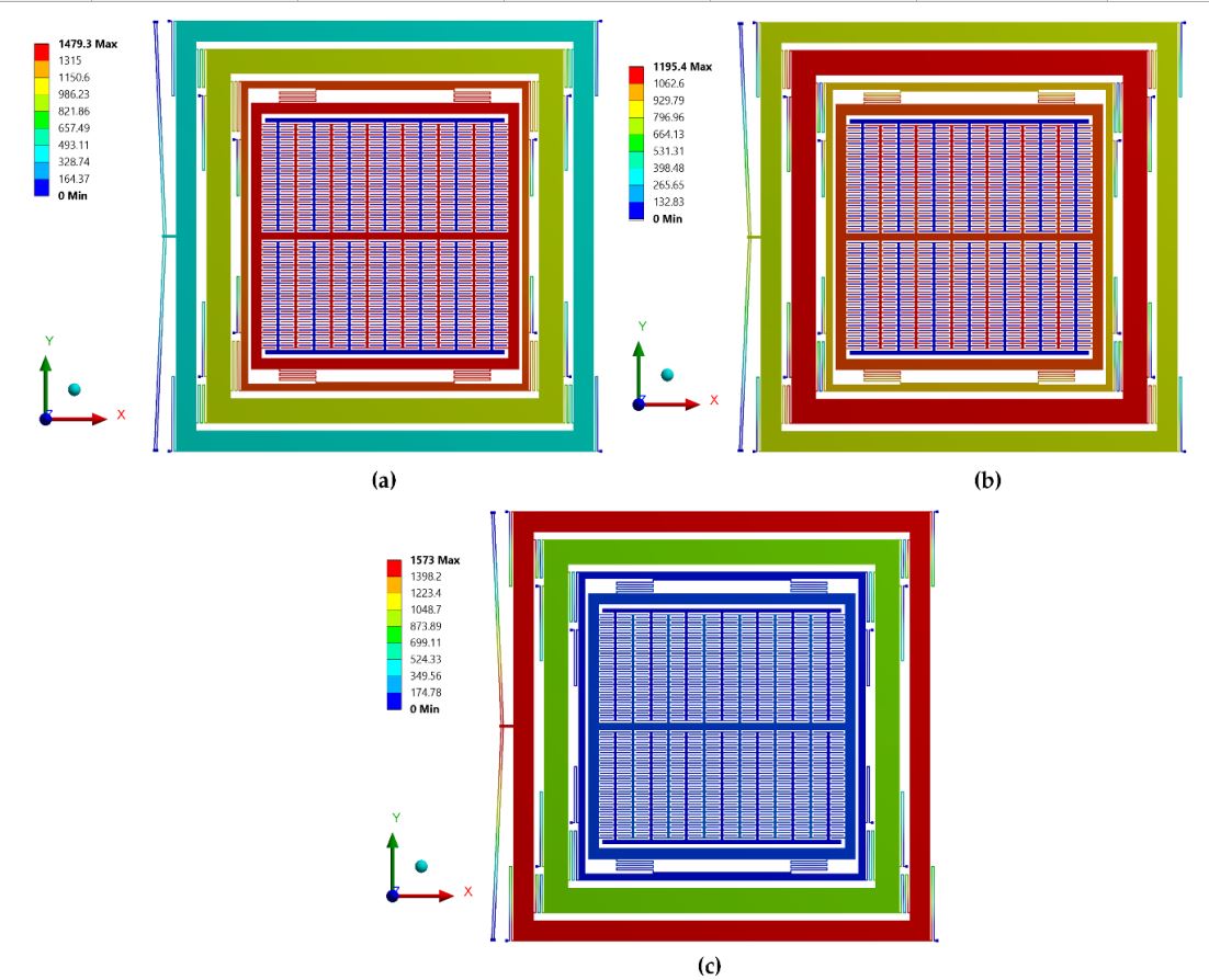
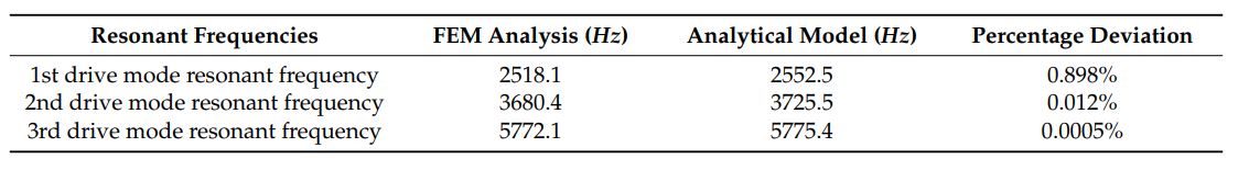
mode shapes with their associated resonant frequencies are shown in Figure 14. Table 3 shows the
comparison of the drive mode resonant frequencies obtained using FEM analysis to that obtained
using an analytical model. The percentage deviation is less than 1%, thus validating the accuracy of
the developed analytical model.The frequency at which the system oscillates with maximum amplitude in the absence of any external force is
known as natural or resonance frequency. For the operation of MEMS accelerometer, an in-plane oscillation of the proof
mass is required. Hence, modal analysis is performed to determine the natural frequency and corresponding mode
shape of the MEMS accelerometer. Fig. 4 shows the first two mode shapes obtained for proposed MEMS accelerometer
design obtained through FEM simulation in the CoventorWare. The first mode is along x-axis with frequency
of 3472.13 Hz. The second mode is along z-axis with frequency of 5302.75 Hz, which shows that the two modes are
well separated in frequency.
a FEM-based natural frequency analysis is carried out. The boundary conditions and material
properties are input parameters while mode shapes and resonant frequencies are the output responses of the modal analysis. The structural parts are modeled using Solid 98 elements. The optimized mesh
size is selected based on patch conforming algorithm for tetrahedrons method control. The desired
mode shapes with their associated resonant frequencies are shown in Figure 14. Table 3 shows the
comparison of the drive mode resonant frequencies obtained using FEM analysis to that obtained
using an analytical model. The percentage deviation is less than 1%, thus validating the accuracy of
the developed analytical model.The frequency at which the system oscillates with maximum amplitude in the absence of any external force is
known as natural or resonance frequency. For the operation of MEMS accelerometer, an in-plane oscillation of the proof
mass is required. Hence, modal analysis is performed to determine the natural frequency and corresponding mode
shape of the MEMS accelerometer. Fig. 4 shows the first two mode shapes obtained for proposed MEMS accelerometer
design obtained through FEM simulation in the CoventorWare. The first mode is along x-axis with frequency
of 3472.13 Hz. The second mode is along z-axis with frequency of 5302.75 Hz, which shows that the two modes are
well separated in frequency.
After the identification of the required mode shape and
resonance frequency from the modal analysis, a harmonic
analysis is carried to determine the amplitude response of the
MEMS accelerometer at different input acceleration
magnitudes over a range of frequencies. The accelerometer is
given an acceleration of magnitude ranging from 10-50g and
a set of frequency response curves are obtained as shown in
Fig. 5. It can be depicted from the curves that proof mass
moves with a maximum displacement at resonance. For the
current case, the accelerometer is desired to work in the linear
region i.e., ω≪ωn, and in this region the response is linear
with frequency bandwidth of DC-300 Hz.
Matlab Code
For MATLAB code, please click the Link-1
CAD Model
For CAD Model, please click the Link-2