Design and Analysis of a High-Gain and Robust Multi-DOF Electro-thermally Actuated MEMS Gyroscope
Description
the design and analysis of a multi degree of freedom (DOF) electro-thermally actuated non-resonant MEMS gyroscope with a 3-DOF drive mode and 1-DOF sense mode system. The 3-DOF drive mode system consists of three masses coupled together using suspension beams. The 1-DOF system consists of a single mass whose motion is decoupled from the drive mode using a decoupling frame. The gyroscope is designed to be operated in the flat region between the first two resonant peaks in drive mode, thus minimizing the effect of environmental and fabrication process variations on device performance. The high gain in the flat operational region is achieved by tuning the suspension beams stiffness. .
A detailed analytical model,
considering the dynamics of both the electro-thermal actuator and multi-mass system, is developed.
A parametric optimization is carried out, considering the microfabrication process constraints of the
Metal Multi-User MEMS Processes (MetalMUMPs), to achieve high gain. The stiffness of suspension
beams is optimized such that the sense mode resonant frequency lies in the flat region between the
first two resonant peaks in the drive mode. The results acquired through the developed analytical
model are verified with the help of 3D finite element method (FEM)-based simulations. The first
three resonant frequencies in the drive mode are designed to be 2.51 kHz, 3.68 kHz, and 5.77 kHz,
respectively. The sense mode resonant frequency is designed to be 3.13 kHz. At an actuation voltage
of 0.2 V, the dynamically amplified drive mode gain in the sense mass is obtained to be 18.6 µm. With
this gain, a capacitive change of 28.11 f F and 862.13 f F is achieved corresponding to the sense mode
amplitude of 0.15 µm and 4.5 µm at atmospheric air pressure and in a vacuum, respectively.
Operating Principle
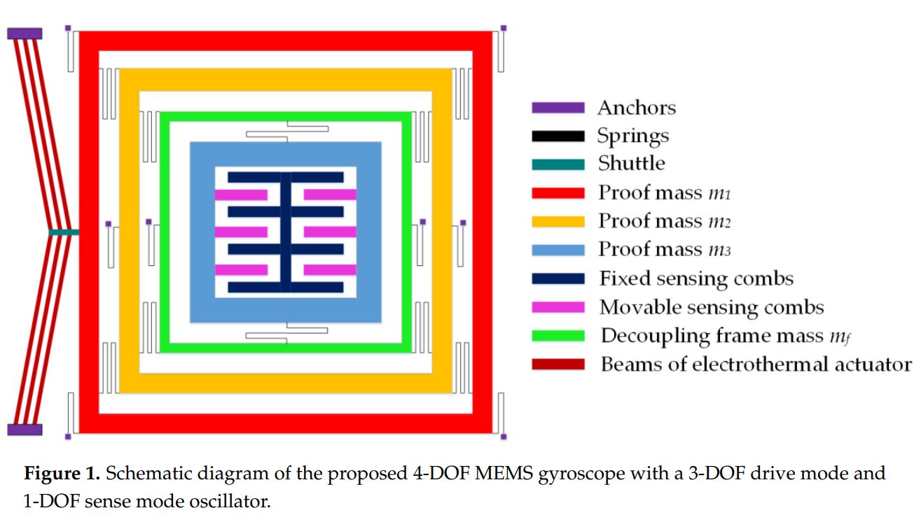
Figure 1 shows the schematic of the proposed MEMS gyroscope with a 3-DOF drive mode and
1-DOF sense mode. The first mass m1 which is the drive mass is excited by an external force in the
drive direction using the V-shaped electro thermal actuator. The second mass m2 transfers the dynamic
energy from the mass m1 to mass m3 which acts as a final oscillating mass. The masses m1 and m2 are
free to move in the drive direction but constrained to move in the sense direction by means of elastic
springs. The sense mode oscillations of mass m3 are decoupled from the drive direction oscillations by
means of a decoupling frame mf to minimize instabilities due to dynamical coupling between sense
and drive modes. Thus, masses m1, m2, and combination of (mf + m3) form a 3-DOF drive mode
while m3 being free to oscillate in the sense acts as a 1-DOF sense mode oscillator. The sense direction
oscillation of the mass m3, corresponding to an input angular velocity, is designed to be measured by
using parallel plate sense combs.
Analytical Modeling
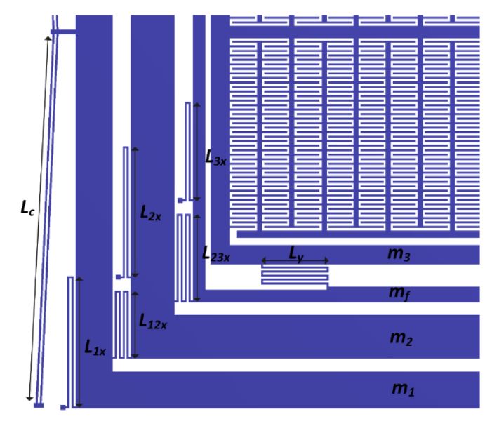
The designed suspension system configuration of the proposed gyroscope allows the masses
m1 and m2 to move only in the drive direction but restricted their motion in the sense direction. The
mass m3 is allowed to oscillate in both the drive and sense direction which are orthogonal to each
other. The suspension system configuration of the proposed gyroscope dynamical model is shown in
Figure below.
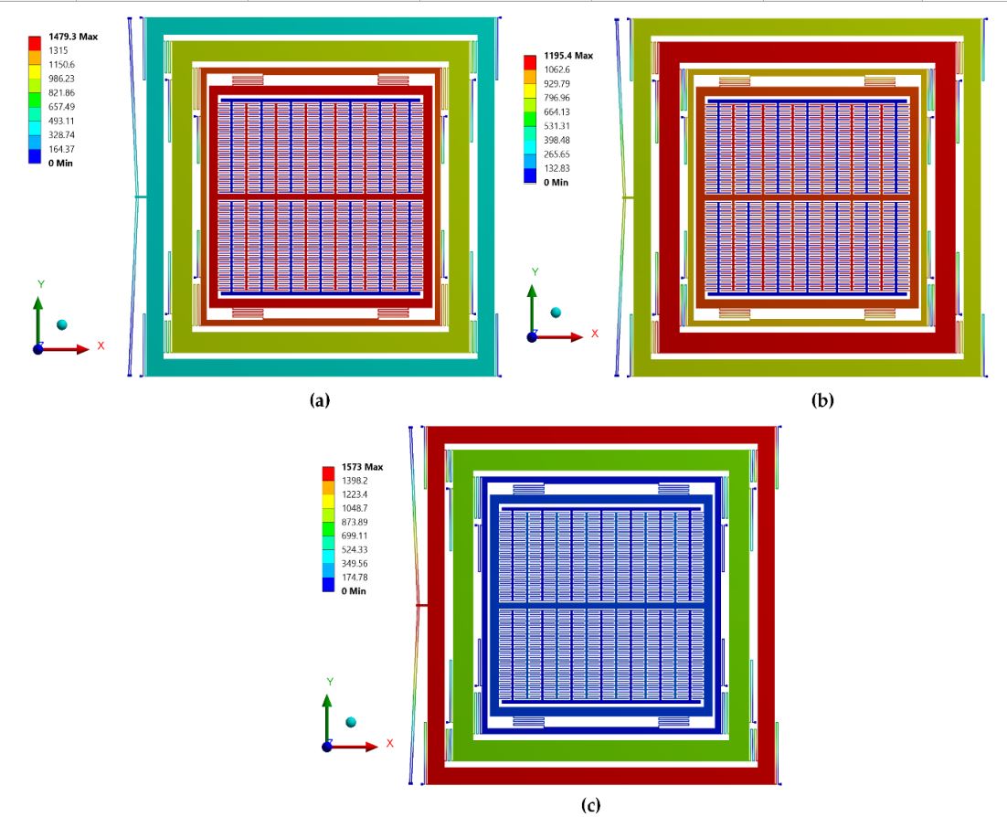
FEM Analysis
a FEM-based natural frequency analysis is carried out. The boundary conditions and material
properties are input parameters while mode shapes and resonant frequencies are the output responses
of the modal analysis. The structural parts are modeled using Solid 98 elements. The optimized mesh
size is selected based on patch conforming algorithm for tetrahedrons method control. The desired
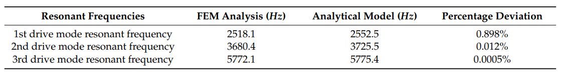
mode shapes with their associated resonant frequencies are shown in Figure 14. Table 3 shows the
comparison of the drive mode resonant frequencies obtained using FEM analysis to that obtained
using an analytical model. The percentage deviation is less than 1%, thus validating the accuracy of
the developed analytical model.
Matlab Code
For MATLAB code, please click the Link-1
CAD Model
For CAD Model, please click the Link-2