Surface roughness effects on electromechanical performance of RF-MEMS capacitive switches
Description
The effect of surface roughness on the electromechanical performance of radio frequency micro-electromechanical system (RF-MEMS) based capacitive switches is an important reliability concern. This paper presents a finite element method (FEM) based simulation methodology for the estimation of surface roughness effects on the electromechanical characteristics of parallel plate capacitive RF-MEMS switch. The important electromechanical characteristics considered for the analysis of surface roughness effect include up-state capacitance, down-state capacitance, pull-in voltage, pull-in gap and switching time of RF-MEMS switch. A simple roughness model is employed consisting of semi-circles of constant radius along the surface of an RF-MEMS switch. It is shown that there are significant, but predictable shifts in electromechanical characteristics of RF-MEMS switch due to surface roughness. The results illustrate that the normalized value of up-state capacitance and pull-in gap increases, whereas the values of downstate capacitance, pull-in voltage and switching time decreases with an increase in surface roughness. The change in pull in voltage for an initial air gap of 0.4 μm and roughness of 50 nm is around 28.5% which is about quarter the value of voltage required for the actuation of smooth surface RF-MEMS switch. The results obtained through FEM based analysis in this work are in good agreement with the adopted analytical model and experimental results presented in literature.
.
Operating Principle
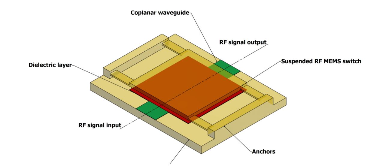
The 3D schematic of the electrostatically actuated RF-MEMS capacitive switch is shown below. The
structure of the RF-MEMS switch is implemented on a coplanar waveguide (CPW) and consists of a suspended metal bridge overlapping the
RF transmission line. The transmission line is covered with an insulating layer known as dielectric. The top suspended bridge is supported by four beams anchored to the RF grounded electrodes. In the
normal configuration, the top suspended bridge is in upstate and due to
very low value of capacitance, the signal propagates through switch
with negligible losses. On application of DC voltage between the suspended bridge and dielectric layer, the bridge moves downward towards the transmission line. If the value of actuation voltage is high
enough and the initial distance d between the suspended bridge and
signal line is reduced to ds = 2d/3, the pull-in phenomena occurs. It
causes the suspended bridge to make a contact with dielectric layer
reducing the gap to ideally become zero.
Modeling
Analytical models are helpful at the design stages of MEMS devices
for predicting certain design parameters and providing close approximations to the static and dynamic behavior. However, for an accurate
depiction of the multiphysics behavior of MEMS devices modern numerical methods such as FEM simulations are extensively being employed. The governing principles of RF-MEMS switches are based on
electromechanics, so the analysis of electromechanical characteristics
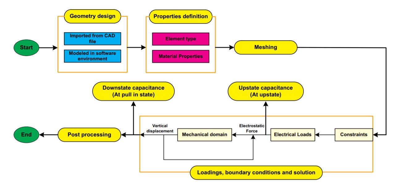
of RF-MEMS switch is carried out using FEM based coupled electrostructural simulations. Fig. 2 shows the layout for the implemented
FEM methodology. The FEM model is divided into two basic parts i.e.
the switch structure and the initial air gap in between top suspended
bridge and dielectric layer. The beams and suspended bridge are
modeled using the 8 node Solid185 element. The mechanical structural
constraints are applied on the supporting beams end to restrict the
displacement. The initial air gap between the top suspended plate and
bottom dielectric layer is modeled using the 20 node Solid226 elements. Since the top bridge plate is symmetric with respect to center
thus to minimize the meshing complexity, only a quad portion is
modeled in the FEM simulations. With an applied actuation voltage, the
resulting electrostatic force moves the bridge plate towards the bottom
dielectric layer.
The main performance parameters studied through FEM simulations
for the RF-MEMS switch, with and without incorporating surface
roughness include the up and downstate capacitance, pull in voltage,
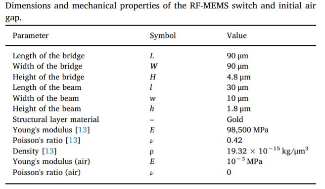
pull in gap and switching time. The table below shows the geometric parameters
and material properties used for the FEM simulations of the RF-MEMS
switch assuming thin film gold as a structural layer.
Case of smooth surface RF-MEMS switch
To validate the accuracy of the FEM based simulations, initially
electromechanical characteristics of the smooth surface RF-MEMS
switch including pull-in voltage, up-state capacitance and pull-in gap
are obtained using two different techniques in Multiphysics ANSYS
module including transducer elements (Trans126) and coupled-field
simulations. Trans126 elements provide a reduced order FEM modeling
of the coupled electrostatic ̶ structural interaction utilizing the form of
lumped elements. The results obtained through Trans126 and coupledfield simulations are validated through well-established analytical
models for smooth surface RF-MEMS switches. Figure (a) shows the effect of changing initial air gap distance between the top suspended
bridge and bottom dielectric layer on the pull-in voltage value. The
results perfectly follow the fact that pull-in voltage value increases nonlinearly with increasing initial air gap between the top suspended
bridge and bottom dielectric layer. Thus, validating the accuracy of the
FEM simulations using both Trans126 and coupled-field simulations.
Figure (b) shows that the up-state capacitance values vary non-linearly
with increasing initial air gap value between the suspended bridge and
dielectric layer. Figure (b) also shows an abrupt change in capacitance
value as soon as air gap starts decreasing. With an air gap change from 1 μm to 0.4 μm the change in capacitance is approximately 2.5 times
compared to the value at 1 μm. This indicate significance of initial air
gap on performance of RF-MEMS switch since the capacitance in turn
will determine pull-in voltage and pull-in gap of RF-MEMS switch.
Figure (c) shows that the variation in the pull-in bridge displacement
(pull-in gap) varies linearly with the increasing initial air gap value
between the top suspended bridge and bottom dielectric layer. However, for higher values of the initial air gap there is a significant mismatch between the analytical and FEM simulation results..
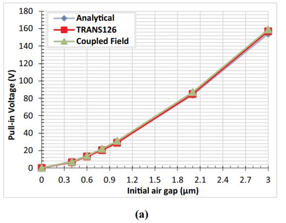
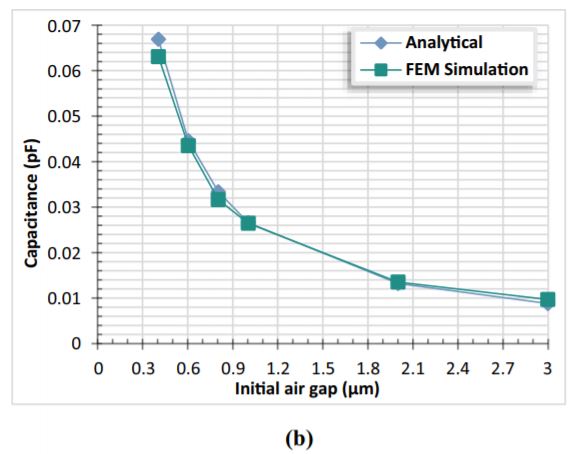
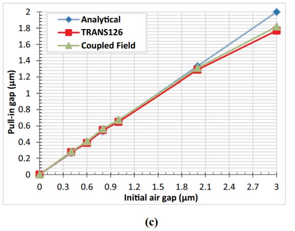
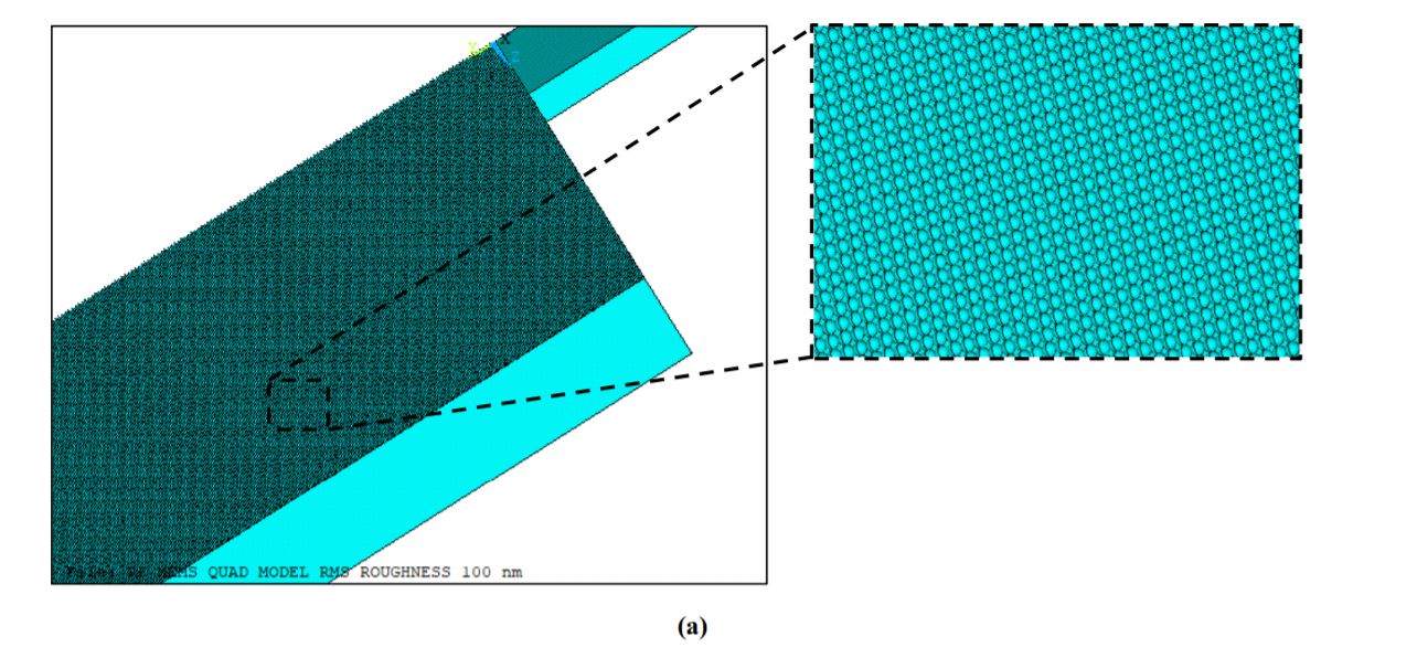
Figure below (a) shows the quad RF-MEMS switch model with surface
roughness implemented in the FEM simulations. The figure (b) below shows the
normalized values of upstate capacitance values obtained by varying
initial air gap values. The normalized value of upstate capacitance increases with the increase in the semi-circle radius. The normalized
upstate capacitance value i.e. 1.82 obtained by considering roughness
of 100 nm for an initial air gap of 0.4 μm is about twice the value of
capacitance obtained for a smooth surface RF-MEMS switch.
The below figure shows the comparison of the results obtained.
The upstate capacitance is experimentally measured as a function of
applied voltage from the upstate to the pull in point
FEM Analysis
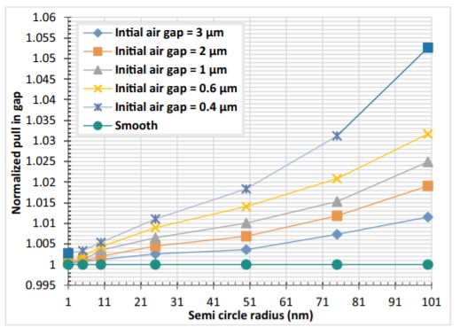
The FEM analysis is performed for rough surface RF-MEMS switch
with thin film gold as structural layer by varying the initial air gap
values from 3 μm to 0.4 μm and semi-circle radius from 100 nm to
10 nm. The graphs for comparison of pull-in voltage and pull-in gap for
different values of surface roughness and initial air gap values are
shown in figure below.
The normalized value of pull-in voltage decreases
with an increase in the radius of semi-circles and results can be seen in figure below
the effect of R/d ratio on the pull-in gap for the RFMEMS switch obtained through coupled-field FEM simulations can be seen below.