Microfabrication Process-Driven Design, FEM Analysis and System Modeling of 3-DoF Drive Mode and 2-DoF Sense Mode Thermally Stable Non-Resonant MEMS Gyroscope
Description
Microfabrication process-driven design of a multi-degree of freedom (multi-DoF) non-resonant electrostatic microelectromechanical systems (MEMS) gyroscope is presented by considering the design constraints of commercially available low-cost and widely-used silicon-on-insulator multi-user MEMS processes (SOIMUMPs), with silicon as a structural material.
The proposed design consists of a 3-DoF drive mode oscillator with the concept of addition of a collider
mass which transmits energy from the drive mass to the passive sense mass. In the sense direction,
2-DoF sense mode oscillator is used to achieve dynamically-amplified displacement in the sense
mass. A detailed analytical model for the dynamic response of MEMS gyroscope is presented and
performance characteristics are validated through finite element method (FEM)-based simulations.
The effect of operating air pressure and temperature variations on the air damping and resulting
dynamic response is analyzed. The thermal stability of the design and corresponding effect on
the mechanical and capacitive sensitivity, for an operating temperature range of −40 ◦C to 100 ◦C,
is presented. The results showed that the proposed design is thermally stable, robust to environmental
variations, and process tolerances with a wide operational bandwidth and high sensitivity. Moreover,
a system-level model of the proposed gyroscope and its integration with the sensor electronics is
presented to estimate the voltage sensitivity under the constraints of the readout electronic circuit.
Structural Design
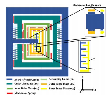
Figure 1 shows the proposed multi-DoF MEMS gyroscope design with a 3-DoF drive mode
and 2-DoF sense mode oscillators. The drive and sense masses are connected to each other using
serpentine-shaped mechanical springs. These springs allow the displacement of the masses in the desired direction only, thus minimizing the cross-axis displacement. The oscillations in the drive
axis (x-axis) are obtained through a comb drive-based electrostatic actuator which is attached to the
outer mass m1. The combination of mass m3a and m3b along with the decoupling frame of mass mf ,
acts as a final vibration absorber m3. For an applied actuation voltage to the electrostatic actuator,
a dynamically-amplified displacement is achieved in the mass m3 while the mass m2 transfers the
dynamic energy from mass m1 to m3. For an input rotation in the z-axis, a Coriolis force is generated
in the orthogonal axis to drive and rotation axes i.e., y-axis. This leads to a displacement in the
2-DoF sense mode oscillator consisting of a mass m3a and m3b, which are connected to each other
through mechanical springs. The mass m3b acts as a vibration absorber for the mass m3a in the sense
direction, resulting in a dynamically-amplified displacement in the mass m3b with respect to mass m3a
corresponding to the Coriolis force. The displacement in the mass m3b is sensed using parallel plates,
which are arranged in a gap–antigap-based differential configuration [27]. The small gap (d1) is kept as
3 µm while the large gap (d2) value is 9 µm. The change in capacitance in the sensing parallel plates
has an inverse relationship to the initial air gap between the plates. The minimum air gap allowed by
the microfabrication process is 2 µm. However, to meet the microfabrication process constraints and to
minimize the Brownian noise and air damping effect, the initial small gap (d1) is considered to be 3 µm.
To minimize the effect of sudden mechanical shock, semicircle-shaped end stoppers are designed at the
end of the masses adjacent to the anchors. Table 2 shows the main design parameters of the multi-DoF
Micromachines MEMS gyroscope.
Analytical Modeling
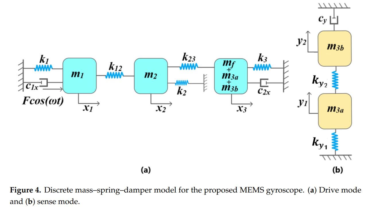
Figure 4a shows the 3-DoF drive mode mass–spring–damper model representation of the proposed
MEMS gyroscope. For an input driving force Fcos(!t), displacement of mass m1, m2 and sense mass
(m3a, m3b, mf ) is represented by x1, x2, and x3 respectively. The mass m1 and sense mass (m3a, m3b,mf ) are anchored to the substrate through mechanical springs k1 and k3 respectively. The mass
m2, attached to the mass m1 and sense mass (m3a, m3b, mf ) through mechanical springs k12 and k23,
respectively, acts as a collider mass and transfers the dynamic energy from the mass m1 to the sense
mass (m3a, m3b, mf ). The mass m2 is also connected to the substrate through mechanical spring k2.
The k2 allows us to optimize the dynamic displacement amplification between the mass m1 and sense
mass (m3a, m3b, mf ) and the width of the flat operational region between the resonance peaks of drive
mode oscillators. The air damping between the actuator combs attached to the mass m1 and
sensing parallel plates attached to sense mass (m3a, m3b, mf ) are represented by c1x and c2x, respectively.
Figure 4b shows the 2-DoF sense mode mass–spring–damper model of the MEMS gyroscope. The mass
m3b acts as dynamic vibration absorber for the mass m3a and both masses are coupled through the
mechanical spring ky1. The mass m3a is attached to the decoupling frame mf , which acts as an anchor,
through mechanical spring ky2 and the air damping in the sensing parallel plates attached to the mass
Micromachines m3b is represented by cy, 11, x cy.
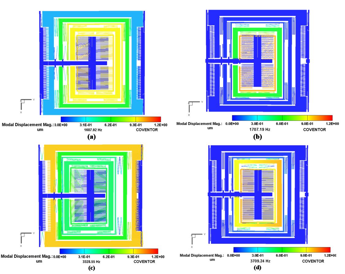
FEM Analysis
To determine the resonant frequency values and corresponding mode shapes for the MEMS
gyroscope, a FEM-based analysis was carried out in the CoventorWare Analyzer module. Figure below shows the desired three drive mode shapes and two sense mode shapes for the MEMS gyroscope. The first,
sixth and tenth modes were in the drive direction with a frequency of 1.608 kHz, 3.329 kHz and
4.822 kHz respectively. The second and seventh modes are in the sense direction with a frequency
of 1.707 kHz and 3.709 kHz respectively. These results show that the two sense mode resonance
frequencies are close to the first two drive mode frequencies, thus making the operational region of the
MEMS gyroscope fall in the flat region between the resonance peaks. The third, fourth and fifth modes
are out of the plane and twisting at 1.79 kHz, 1.9 kHz and 2 kHz respectively. These undesired modes
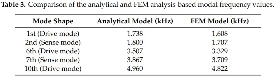
separate from the flat region by at least 200 Hz. Table 3 compares the FEM-based modal analysis results
with the analytical model, which show a close correspondence.
Matlab Code
For MATLAB code, please click the Link
CAD Model
For CAD File-1, please click the Link-1
For CAD File-2, please click the Link-2